Adjusting GPS Networks
By Dr. Robin Steeves
This article describes the usual steps used to adjust a GPS network with GeoLab. A sample GPS network is used to show how your IOB files are normally organized. It's best if you can follow along in your copy of GeoLab while reading through this article,
1. Importing Your Measurements
After the field work has been completed, the first step toward the adjustment process is to get your data into GeoLab's "IOB" format. IOB files are simply text files that contain a number of GeoLab text records - you'll see some examples below.
This step can be done using GeoLab's "Build new project" button from the Project/Setup tab. GeoLab supports many different file formats, and you simply have to select the correct one in the "Import Foreign Format File" dialog as shown in the following image:

2. Organizing Your IOB File
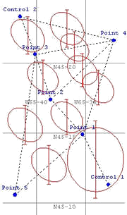
We will use the sample GPS network's IOB file to help with describing how you should organize your data. Note that we will not use a geoid model in this particular adjustment, but you do this with a GFIL record, as will be shown in another article.
The following general IOB file structure can be used for any type of adjustment you wish to perform in GeoLab (the sections used are in the same order as they appear in our actual IOB file, and the line numbers for each section are as follows:
Options (lines 1 - 21): The title record (TITL), ellipsoid record (ELIP), map projection records (QUAD and XSTR in our case), and any option records you wish to use.
Control Coordinates (lines 23 - 25): Control station coordinates are listed here, with the specification of which coordinates are to be fixed (described briefly below).
Initial Coordinates (lines 27 - 32): Initial coordinates for non-control (e.g. new) stations are listed here, with no coordinates fixed.
Measurements (lines 34 - 115): All measurements are listed here, in any order.
Geoid (not used in this sample): The GFIL record (which specifies a GSP file to use for geoid interpolation) normally appears in this section.
The "Import Plugins" section lists all the installed import plugins. In the above image, the "Leica SKI Pro" plugin is selected. Once you have the correct plugin selected, click the "Import Text File(s)" button, select the files your instrument produced, and click the "Open" button. GeoLab will convert your coordinates (if any) and measurements into a new IOB file. Note that for Trimble's SSF files, you must first load those files into TGO (Trimble Geomatics Office) and then export the data into Trimble's "Data Exchange Format" which GeoLab can import directly.
Note that you don't have to (and you normally should not) edit the lines of the IOB file manually. You should always use GeoLab's Assistant tab to add and edit records.
3. The Minimal Constraint Adjustment
When you have your IOB file set up as described above, you are ready to start adjusting the network. The first adjustment you do should always be a minimal constraint adjustment. This allows you to analyze the quality of your measurements without any distortions that may be caused by fixing all of your control stations.
For our network, we fix one control station for the minimal constraint adjustment. The IOB file we provide is set up for the over-constrained adjustment, with two control stations fixed.
For the minimal constraint adjustment, the following lines were used in the "Control Stations" section:
PLH 111 Control 1 n 45 11 20.034560 w 65 32 42.982340 238.234 m
PLH 000 Control 2 n 45 23 19.675430 w 65 41 38.565290 186.238 m
Note that we fixed only the first control point in the records above (the "111" field tells GeoLab to fix all three coordinates (latitude, longitude, and height) of the station "Control 1"). The minimal constraint adjustment is where you will normally do most of your adjustment work. The normal procedure for performing this adjustment is as follows:
1. Perform the adjustment using the "Process main IOB file..." button in the Assistant tab.
2. Analyze the standardized residuals (see below) and edit the measurements if necessary. If measurements are edited, do steps 1 and 2 again.
3. Once the standardized residuals are all acceptable (see below), use the estimated variance factor from the adjustment listing in a VSCA record (measurement variance scale factor) at the beginning of the measurements section (see the IOB file for an example) and then run the minimal constraint adjustment one more time (this last adjustment is done to record the results of the minimal constraint adjustment).
The analysis of the standardized residuals is the most important quality control process in an adjustment. To discuss this further, we will use a portion of the listing file (GeoLab output text file) from our GPS adjustment as an example:

The standardized residuals are listed at the right of the first line for a measurement. For example, the GPS vector measurement listed has a DZCT standardized residual of -3.4639. Note that the "critical value" for the standardized residuals is given at the top of the listing page ("critical value = 2.799"). This is the theoretical upper limit for the magnitude of acceptable standardized residuals, and GeoLab will underline (with "^^^^...") any standardized residual greater in magnitude than this critical value (i.e. the measurement is "flagged" for possible removal). Normally there will be only a few such "bad" measurements.
4. Using the Adjustment Summary Dialog
When an adjustment is finished, GeoLab displays the "Network Processing Completed" dialog. When you click the OK button, GeoLab will display the Adjustment Results Summary dialog as follows:

ote that the Standardized Residuals section (in bottom left of this dialog) shows that two standardized residuals are larger than 2.7. If you decide that the first observation should be removed from the adjustment, you can double-click the value in the list and GeoLab will move the text caret in the listing window to the location of the measurement's standardized residuals. You can then see which observation group the measurement is in, and easily find that group in your IOB file.
To remove the measurement, just comment it out (using the F4 key on each line will do that). Once this is done you can re-run the adjustment. You continue in this way until you have found and removed all "bad" measurements. Note that you should only remove one measurement at a time (the one with the largest standardized residual) because the measurement with the largest residual may be actually causing other measurements to receive large residuals.
After you have removed (commented-out) all "bad" measurements by doing your minimal-constraint adjustments, you should enter the resulting variance factor in the VSCA record (see the IOB file for an example).
5. The Over-Constrained Adjustment
The final step in adjusting our GPS network is the over-constrained adjustment. We start with the IOB file from our minimal constraint adjustment, but now we will fix both control stations in all three dimensions. The "Control coordinates" section was changed to the following for this adjustment:

The main difference you will normally see in the results of the over-constrained adjustment is the value of the estimated variance factor. Because of the additional control coordinate constraints, the variance factor will increase somewhat depending on the relative quality of the control and our measurements.
After ensuring that the standardized residuals are still acceptable in this adjustment, you should revise the VSCA record to reflect the new estimated variance factor (the value in this record should now be changed to the product of the minimal constraint variance factor and the variance factor from this over constrained adjustment).
6. Post-Adjustment Tasks
Once you have completed the over-constrained adjustment, you can use GeoLab's tools to produce other information from the adjustment. For example, you can use the "Station data lister..." button on GeoLab's Project/Tools tab to produce a list of the adjusted coordinates in the CSV (comma separated variable) format, which can be imported into a database or spreadsheet.
This was done for this GPS network adjustment, which produced the following comma-delimited file of station coordinates:

I hope this article is helpful. Please let me know if you have questions or comments! Thanks.