Getting Started with GeoLab
Let's do an adjustment!
To give you a really quick start, we'll go through the initial steps of adjusting one of the sample networks installed with GeoLab. At this point you should have already downloaded the GeoLab ZIP installer and used it to install GeoLab. If not, please do that before continuing with this lesson. Note that you can follow through the procedures below with GeoLab running in "demo" (unlicensed) mode.
Also, please note that this article covers many of the points that were found to be common and helpful answers to questions from GeoLab users over the years, so even experienced GeoLab users may find some useful tips here.
The GeoLab Interface
Run GeoLab now. With GeoLab open, let's first have a brief look at its user interface.
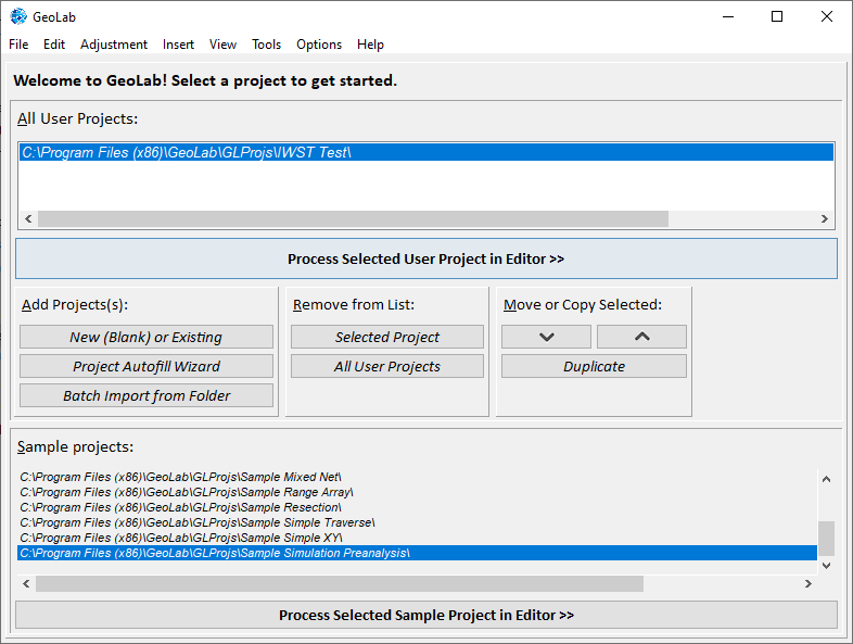
In the image below, note that all available projects are visible on the screen, and the menu bar at the top shows a variety of related toolbars.
Configuring a Project
When you take a closer look at the previous image of the Project/Setup tab, you’ll see that there are two main steps required in order to work on a project:
Click on a desired User or Sample project (sample projects are just those that come with GeoLab to be used as examples); and
Click the appropriate “Process Selected XXXX Project in Editor” button
In the remainder of this document, we will go through this process and look at some related details.
First -What is an IOB File?
One of the main forms of input to GeoLab is a specially-formatted text file we call an "IOB" (an acronym for "Input OBservation") file.
IOB files are simply text files that you can edit with any text editor, but editing them in GeoLab can be easier and more reliable.
Each record (line of text) in an IOB file must be in a specific format with all fields of data in the record in its proper location (within a predefined range of character positions (or columns) in the record. You’ll see an example of an IOB file soon.
Step 1: “Select a project folder”
When you run GeoLab, the first thing you should do is to select the project you wish to work on. You do this by selecting the “project folder” for that project as shown in the above image.
Before continuing with this lesson, please ensure that you have the “Sample Simple Traverse” folder selected.
Step 2: Continue to the Editor
In the lower area of your GeoLab window, you should see the following:
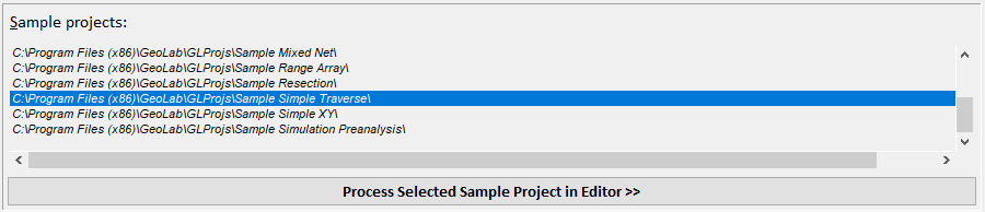
Simply click on the Process Selected Sample Project in Editor button to continue to the main area where you will work on GeoLab projects.
The Fields Editor
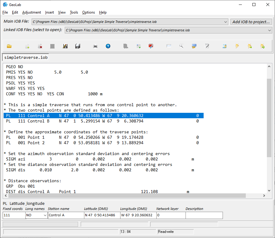
Still in the Assistant tab, click on the first PL record/line of text as indicated in the image. Then look at the "fields editor" section below the text window and you'll see that it contains edit controls for all the fields in the current record. Note that you can edit all of the fields of the PL record in this fields editor.
Records and Fields
Similar to the above line, each GeoLab record consists of a text line starting with a code that tells GeoLab which record it is. Click Here to see a list of all of the available records. Records can be added to a text file by typing a space followed by their 2-4 digit code (eg. PADJ, NE, NEO, CONF). Once a record has been recognized by GeoLab, the easiest way to modify its fields is by clicking that line and using the Fields Editor as shown above.
Adding Records to GeoLab
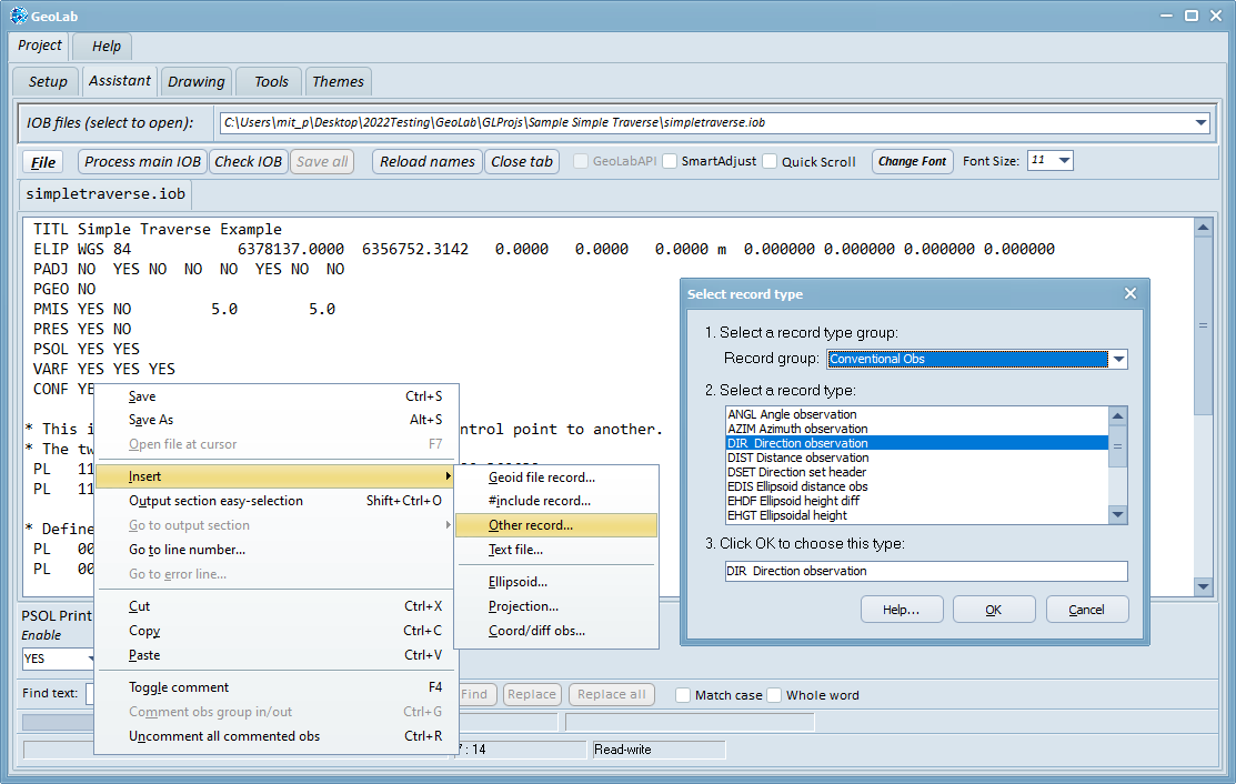
As mentioned above, records can be added by typing a space on a new line followed by the appropriate code. A much easier way to add a record to GeoLab if you do not remember it or its code is to use the Easy Insert Menu. This can be accessed by right-clicking on the Assistant tab and clicking Insert->Other Record…. From here, all available records with their code will be shown for each type of record (Configuration, Parameter, Conventional Observation, Coordinate Observation, Map Projection). Selecting a record and clicking the Ok button will insert that record with its default fields at the current line in your IOB file.
A Closer Look at the IOB File
We'll discuss a recommended layout for IOB files a little later, but first let's have a closer look at the IOB file you have open.
This file contains 32 non-blank lines of text, but the blank lines, and the lines not beginning with a space or a '#' character are treated by GeoLab as comments.
The lines beginning with an asterisk (*) character are comment lines as well (because they don't start with a space or a '#' character).
The first four lines in this IOB files are "option" records, which we can ignore for now.
Commenting Out Lines/Records
Commenting-out lines is easy when you have an IOB file open in GeoLab.
To see how this works, left-click the " PADJ ..." line again, and press the F4 function key. Note that an asterisk character is placed in the first column of the line as shown below. Press the F4 function key again to uncomment the line.

Fixing Station Coordinates
Before we adjust this IOB file, let's examine a few record types. Look for the first line beginning with " NE ...". This is a "Northing and Easting" record. Click on that line and have a look at the fields editor area. The first field in this record in the “Fixed coords” field, and it contains three characters, each specifying whether to fix the latitude/northing, longitude/easting, and height/elevation of the station. If a character is a space or ‘0’ (zero), the coordinate will not be fixed, if the character is a ‘1’ (one) the coordinate will be fixed. Actually, any character other than a space or ‘0’ will result in fixing the coordinate, but ‘1’ has become the standard.
Stations and Measurements
You can see now that the first two NE records in the IOB file specify two control stations with all three coordinates of each fixed.
The next two NE records specify the initial coordinates of the two stations "Point 1" and Point 2", and these two stations have no fixed coordinates.
The adjustment of this traverse will therefore determine the best (most probable) coordinates of these two stations with the given measurements.
Which brings us to the measurements in this project.
Near the end of the IOB file, you can see that there are three "DIST" records, and three "AZIM" records.
The DIST records specify slope (spatial) distance measurements, and the AZIM records specify (astronomic) azimuth measurements. When you look at these records in the Record Editor, you can see the values in their various fields. One of these fields, the "Sigma ID“ field, needs some explanation.
Using Sigma Records
Sigma records begin with the text " SIGM ..." and specify information about a measurement's accuracy that can be re-used in any number of measurement records. For example, to specify the standard deviation and centering errors for a group of distance measurements, we first create a SIGM record with appropriate values for the various fields. Then, when a distance measurement is entered, all we have to do is specify, in the DIST record, the Sigma-ID of the sigma record to use for calculating the standard deviation of that distance measurement.
With this approach we can even leave the standard deviation field of the DIST record blank, because the SIGM record specifies all the information required for calculating the measurement's standard deviation.
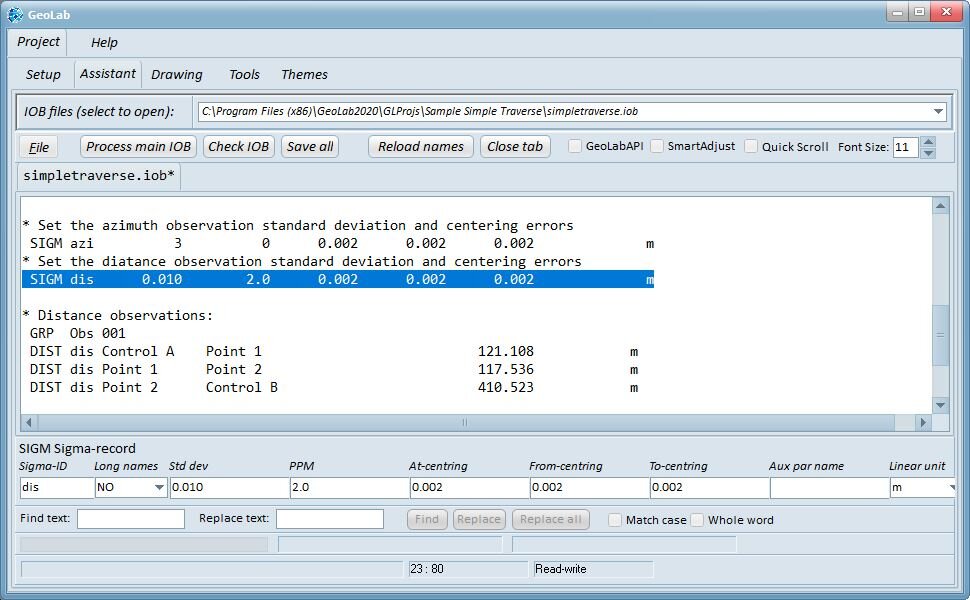
Sigma Record Fields
Left-click on the second SIGM record ("SIGM dis...") and look at the fields in the fields editor. You can see that the distance standard deviation is specified as 0.010 m, with a PPM value of 2.0. Also, instrument and target centering errors are all set to 0.002 m. GeoLab will use all this information to calculate the standard deviation of any measurement that uses the Sigma-ID "dis".
Auxiliary Parameters in Sigma Records
Note that there is an "Aux Par Name" field in the SIGM record. This field is used to add an "auxiliary parameter" to a group of measurements.
For example, if we create an "AUX" record to define an auxiliary parameter group with a "SCA2" (2D scale) parameter, we can assign that parameter to a group of distances by specifying the parameter group name in the "Aux Par Name" field of the SIGM record, and then use that Sigma-ID in all the distances in the group. You can see an example of this in the “Sample EDM Baseline” project.
Using Options Records
Near the top of the IOB file you have open, left-click the "PADJ ..." record again, and press the F7 key.
The PADJ record is an "options" record that specifies the coordinate systems you want your adjusted coordinates listed in.
In the Record Editor you can see that we have chosen to list adjusted coordinates as "NEO" (northing, easting, and orthometric elevation) records, and that we want any adjusted auxiliary parameters ("AUX") listed as well (although we don't have any auxiliary parameters in this particular adjustment).
For more information you can always press the F1 key.
Using Project Options
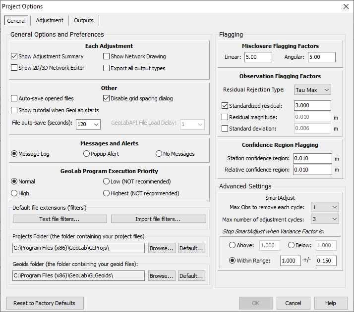
We should have a look at one more important GeoLab tool before we do the adjustment of this IOB file. In the Project/Setup tab, click the "Edit default options" button in the Options section.
The dialog that comes up has five tabs along the top, and each tab contains a number of options that you can use to configure GeoLab.
Click the "Adjustment" tab, and near the bottom-left of the dialog you'll see a drop-down list labeled "Default Linear Unit". Ensure that this is set to "m" for this adjustment.
Explore this dialog a bit to get familiar with the options available to you. To see more information about the items in the Project Options dialog, you can press the F1 function key to open the help dialog.
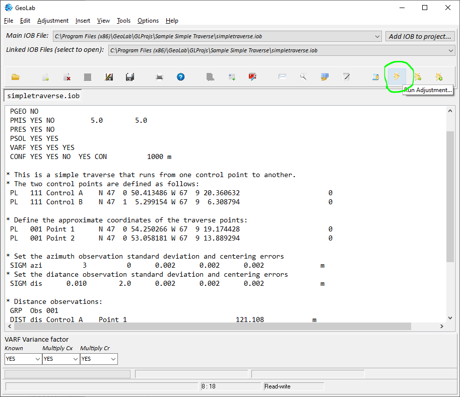
Let's Do the Adjustment!
Close the “Project Options" dialog, then click the Assistant tab to get back to your open IOB file. Now click the “Run Adjustment” hotbar icon, which will start the adjustment of your traverse.
The Adjustment Results Summary Dialog
When you click that toolbar icon, GeoLab starts processing your IOB file, and then displays the "Network Processing Completed" dialog box. Click the OK button in this dialog to close it, and the "Adjustment Summary" dialog will appear.
This dialog is very useful because it displays certain adjustment results related to the quality of your measurements, and the accuracy of your network station coordinates.
For example, in the bottom left portion of this dialog, any standardized residuals greater than a value specified in the Project Options (General Tab). There are none in this case, but we will examine this with examples soon.
Note that you can open an Adjustment Summary dialog for an adjusted network by using the Assistant’s File menu (click the File button).
A Word About GeoLab Preferences
The GeoLab Preferences can be accessed through the Project Options dialog (F2).
This dialog has four tabs across the top. Click the General tab, and a group of controls labeled “Minimum values to display in adjustment summary". These are the settings that determine what is listed in the Adjustment Summary dialog when you do an adjustment.
Press the F1 function key in GeoLab to see more information about this important dialog.
Using the VSCA record
Performing an adjustment with GeoLab is normally quite easy, but we have not yet discussed the full procedure. For example, in the adjustment we performed above, with the variance factor not equal to 1.0, we should scale the variances of our measurements by that value (the estimated variance factor).
However, we will leave the rest of the details of performing adjustments to more realistic networks. Suffice it to point out at this stage that we can apply a scale factor to the variances of the measurements by entering that factor in a VSCA record and re-running the adjustment.
The VSCA record tells GeoLab that the variances of all measurements that follow (and before the next VSCA record) are to be scaled by the factor. When another VSCA record is encountered, the factor is changed to the value on that record, so you can scale the variances of different sets of measurements by different scales. When you want to reset the scale to 1.0 (no scaling), just use a VSCA record with a 1.0 in its field.
The Adjustment Listing File
When you do an adjustment with GeoLab, the results of the adjustment are written to the adjustment listing file which is opened in GeoLab for you after the adjustment is complete. This listing file has the same name as the network's main IOB file, but with the extension "LST".
The main sections of the listing file are as follows:
1.Measurements, parameters, and options summary;
2.Misclosures;
3.Adjustment solutions;
4.Adjusted parameters;
5.Standardized residuals;
6.Statistics Summary; and
7.Confidence Regions.
Using Geoids in GeoLab
We did not use a geoid in the sample adjustment above, but normally the quality of your network adjustment will improve when you use a geoid model. There are two methods for using geoids in GeoLab.
The most popular and easiest method is to use one of the geoids available for download from our web site and add that geoid to your network using a GFIL record. The second method is to use GEOI records in your IOB file. For more information on the GEOI record, please see the GeoLab help files.
A GFIL record has the following form:
GFIL "c:\geoids\mygeoid.gsp“
This records instructs GeoLab to use the specified GSP file for information about the format and coverage of a geoid file. A GSP file is simply a file that contains information about the location, format, and coverage of a geoid file.
Note that both the geoid file and the corresponding GSP file must be downloaded. Also, after you download these two files, you should place them in the same folder on your hard drive, and then use the Geoid Manager (described next) to ensure that the path to the geoid data file is set properly.
The Geoid Manager
To set the correct binary geoid file for your GSP file, open the Geoid Manager in GeoLab by clicking the “Geoid manager” button in the Project/Tools tab.
Click the Open button and browse to the folder where you saved your geoid file and the corresponding GSP file.
When you are returned to the Geoid Manager, click the Browse button to the right of the “Geoid data file” edit box (see the screen shot at the right). Select the geoid data file and click OK. Finally click the Save button and close the Geoid Manager.
You are now ready to use the geoid in your adjustments.

The GFIL Record and Initial Coordinates
When you use a GFIL record, GeoLab will interpolate geoid undulation values from the specified geoid file for any stations that don't already have undulations defined. Remember to place the GFIL record after any initial coordinates you have in your IOB file so that the geoid interpolation will be done using the correct coordinates of the stations.
For the most accurate results when using a GFIL record, you should do the following:
•Place the GFIL record after any initial coordinate records in your IOB file;
•After you have cleaned up any problems with large observation residuals, copy the adjusted coordinates from your adjustment listing file into your IOB file, replacing the previous initial coordinates you were using.
This ensures that the initial coordinates used for geoid interpolation are the most accurate available, thus ensuring that the undulations used for all stations are the best available.
Recommended IOB File Layout
The last topic we'll look at briefly in this document will be a recommended layout for IOB files. This layout has proven useful for performing all sizes of network adjustments. Because it is common to have measurements of different types in a network, we will discuss the IOB file layout in terms of three such groups of measurements.
Let's consider the case where we have imported (using GeoLab's File/Import menu command) two sets of GPS measurements and one set of conventional traverse measurements as described in the following table:

The Main IOB File Layout
The main IOB filename we will use is "MyNetwork.iob". The recommended layout for this file is as follows (note that any line beginning with a period (.) is a comment record):
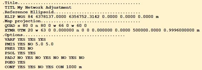
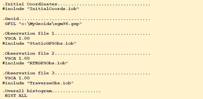
Recommended IOB File Layout
Note that we have used the "#include" record type to insert our three different types of measurements in our main IOB file.
This setup makes it easy to do the adjustment of each measurement group separately by simply commenting out the other two #include records.
For example, if we wish to first do a minimal constraint adjustment using just the first group of measurements, all we have to do is comment out the #include records for the other two groups of measurements.
Also, each group (file) of measurements begins with its own VSCA record, so it is easy to scale the measurements variances/covariance matrices of each group separately.